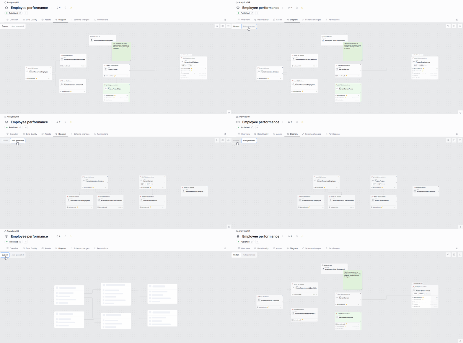
Viewing diagrams in Portal
You can view your ERD diagram directly in Portal, to aid quick understanding of your data source's and asset's structure. Viewable diagrams can be accessed in the object's Diagram tab.
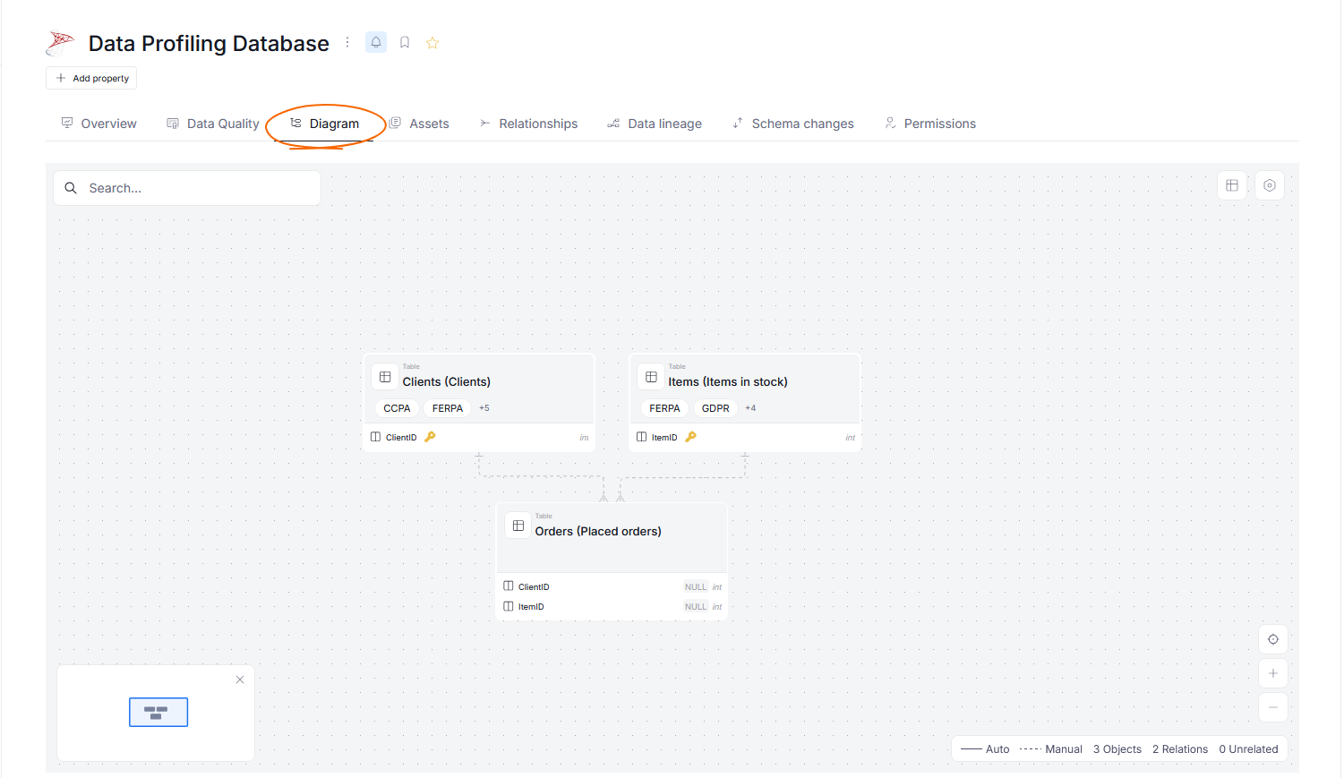
Navigating diagrams
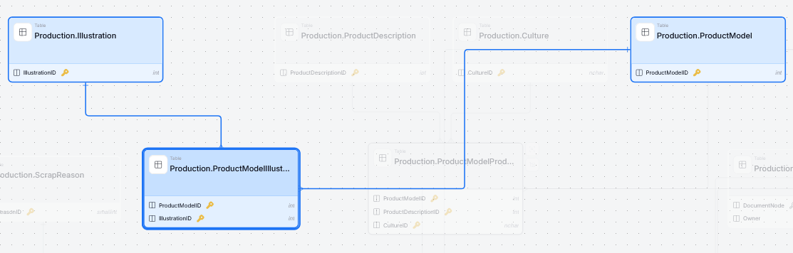
Relationships between objects are represented using crow's foot notation. Relationships between objects within your data source are represented as links. They are drawn either with a solid line (for automatically extracted connections) or a dashed line (for those added manually).
Connections on a diagram
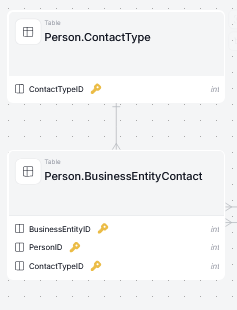
Clicking a link highlights it, along with the columns involved in the relationship it represents.
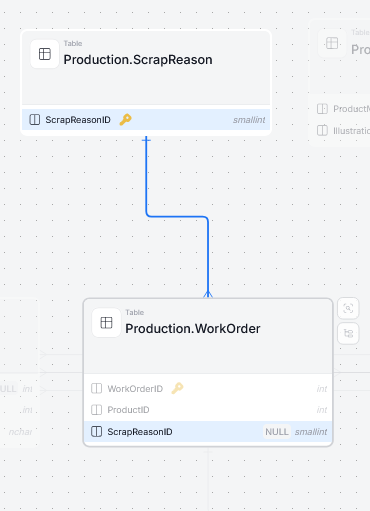
Alternatively, clicking the object itself highlights all links to and from it.
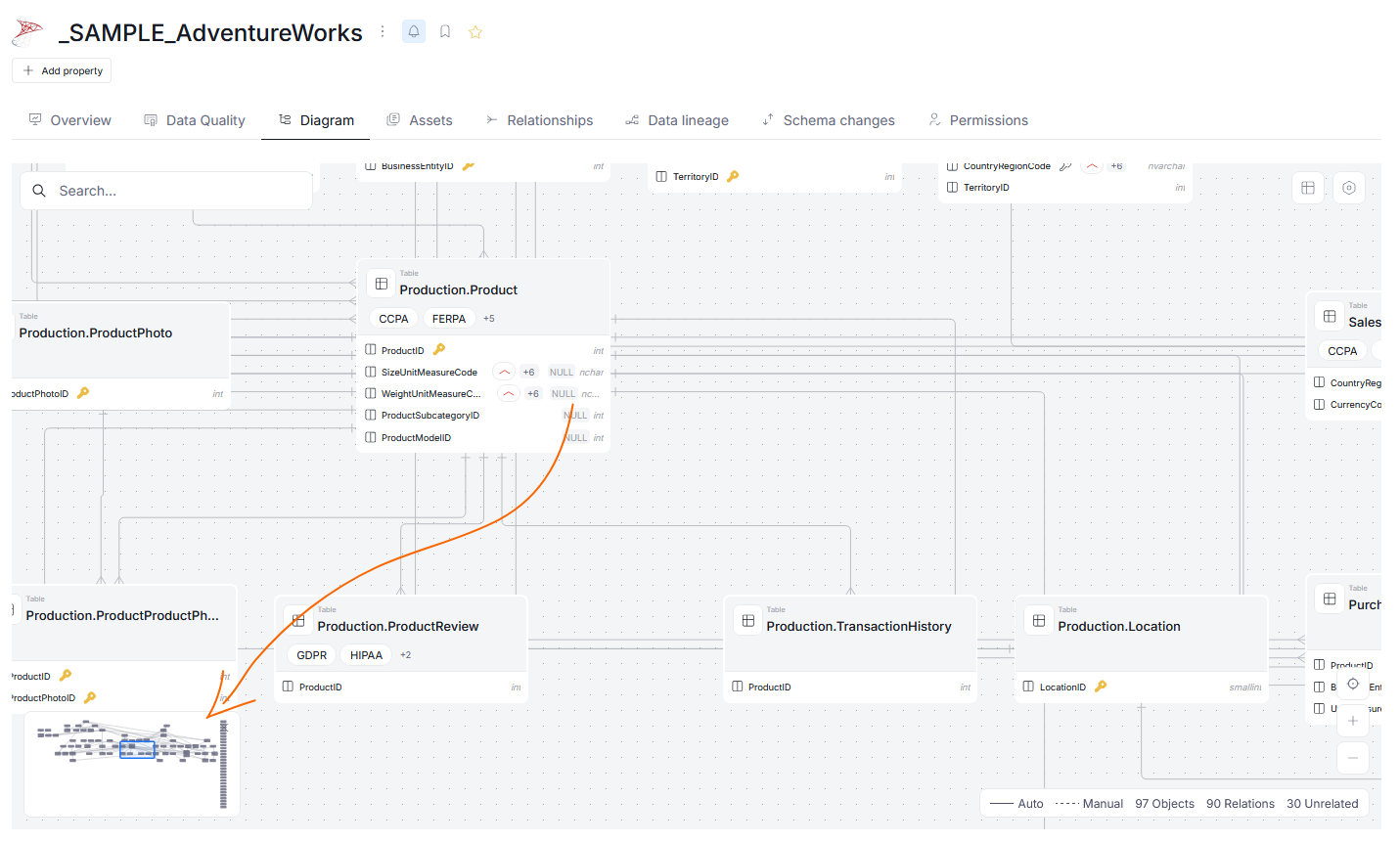
Diagrams for larger databases can be quite extensive, so it is possible that only a part of a diagram can be viewed at a time. You can navigate through larger diagrams by clicking and dragging on the screen — this lets you glide through the diagram and see its other sections. Additionally, you can consult a smaller viewbox located in the bottom left corner to see which section of a diagram you are currently viewing.
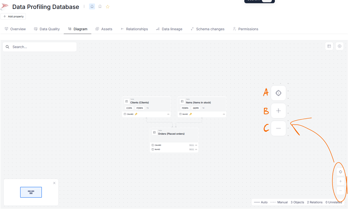
Additionally, you can zoom in and out from the current view using your mouse's scroll wheel, or the dedicated navigation bar in the bottom right part of the screen. The viewport button [A] lets you adjust the diagram to the viewport's size, while the plus [B] and minus [C] buttons let you zoom in and out respectively.
Searching
The search bar in the diagram's top left corner allows you to search for objects by their names or column names.

Unrelated objects
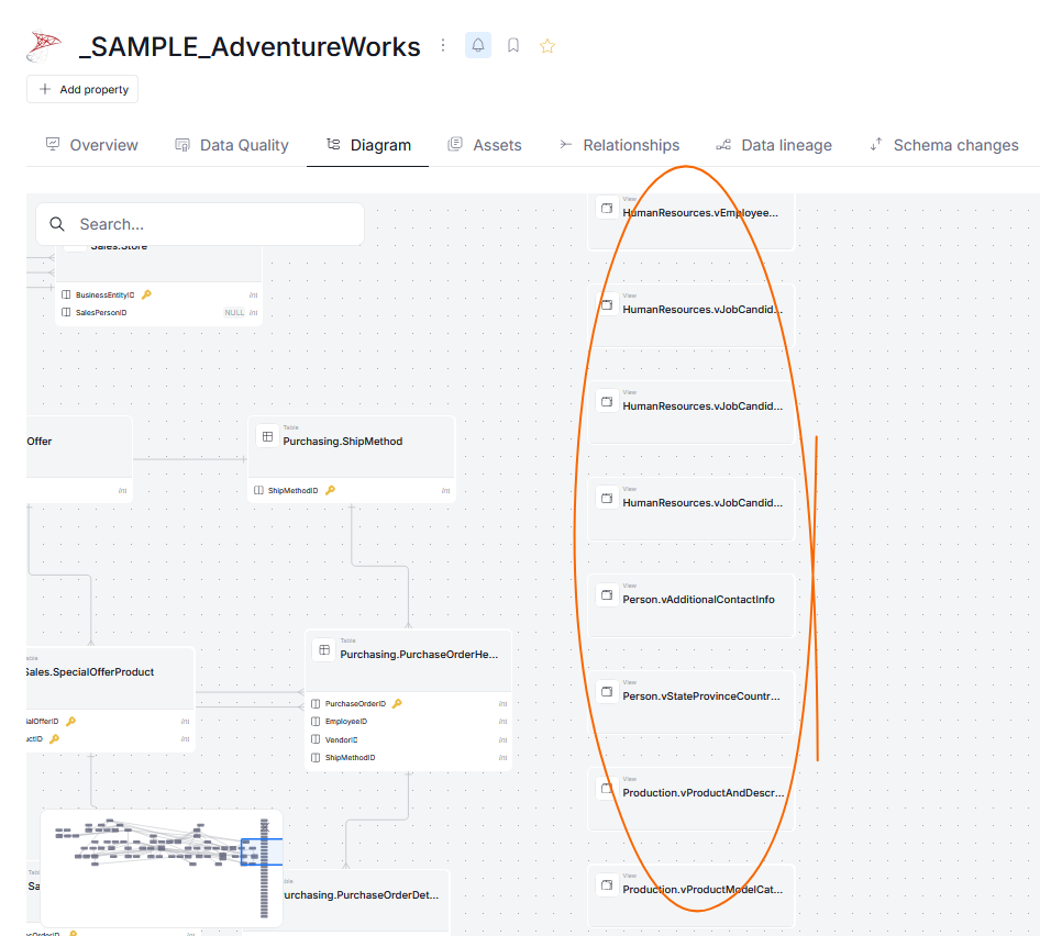
Some objects in a database can have no relationships with other objects. Those objects are displayed in the rightmost section of a diagram and have no links.
Relations panel
ERD diagrams map dependencies between tables that result from key relationships.
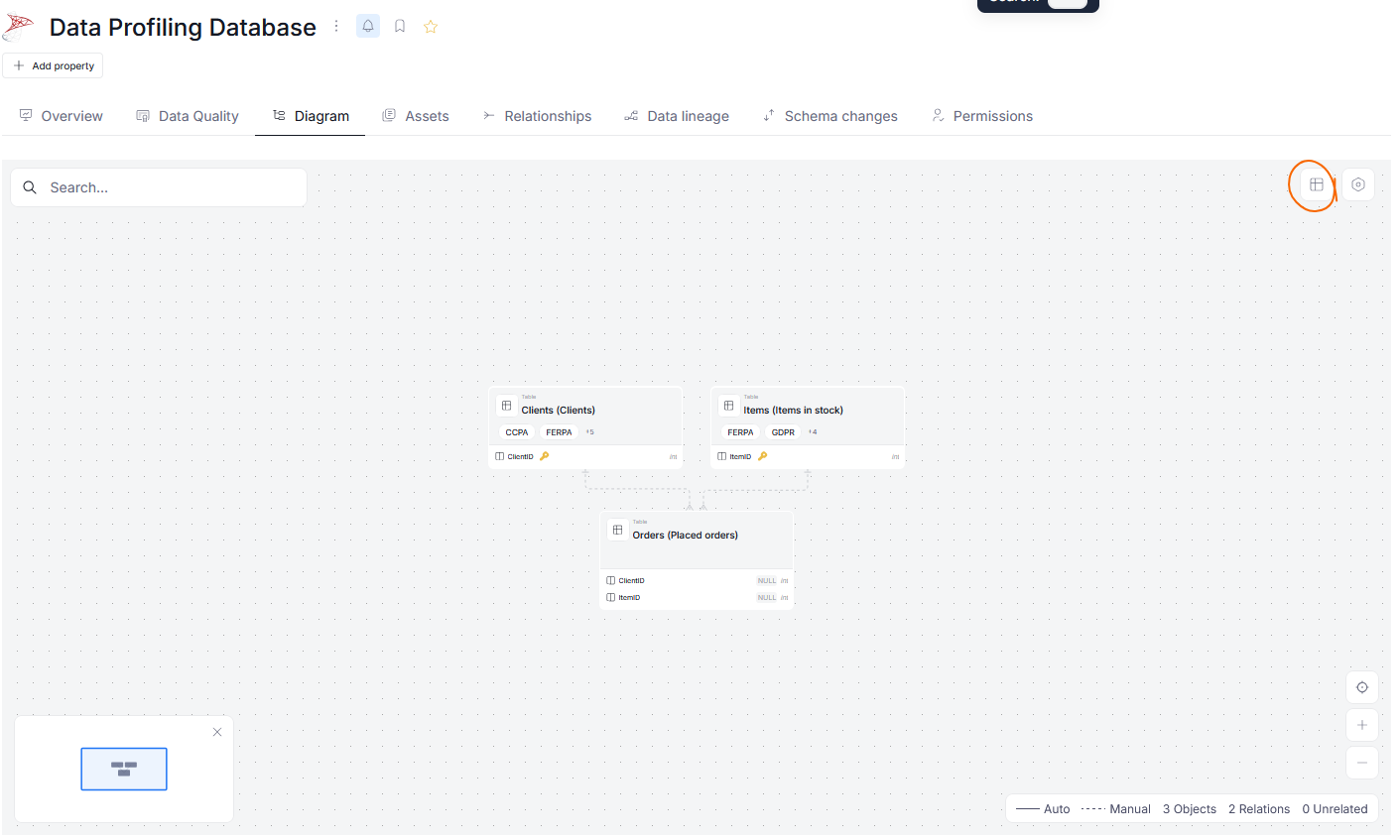
In the Diagram view, you can also look up the relationships between tables in your database. To start viewing them, click the Relations panel button.
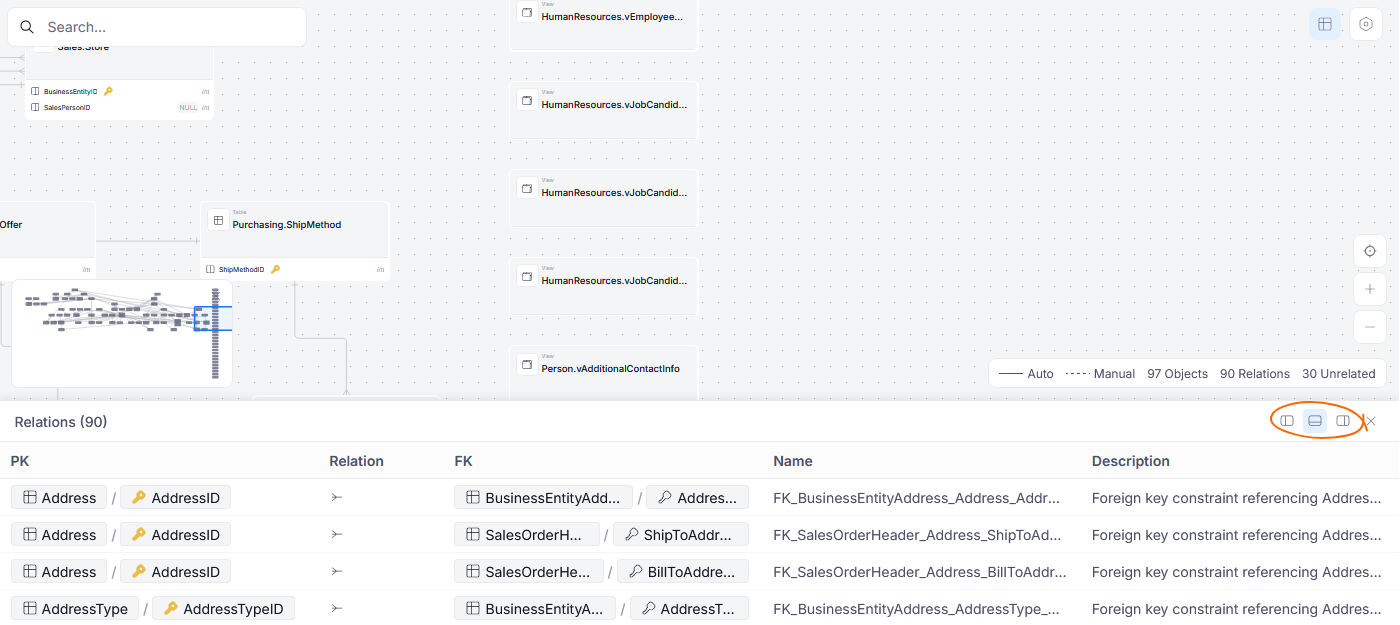
The panel is displayed in the bottom part of the screen by default; however, you can change its position using the dedicated buttons.
By default, all relations are displayed; however, if you highlight a specific object, only its relationships are shown.
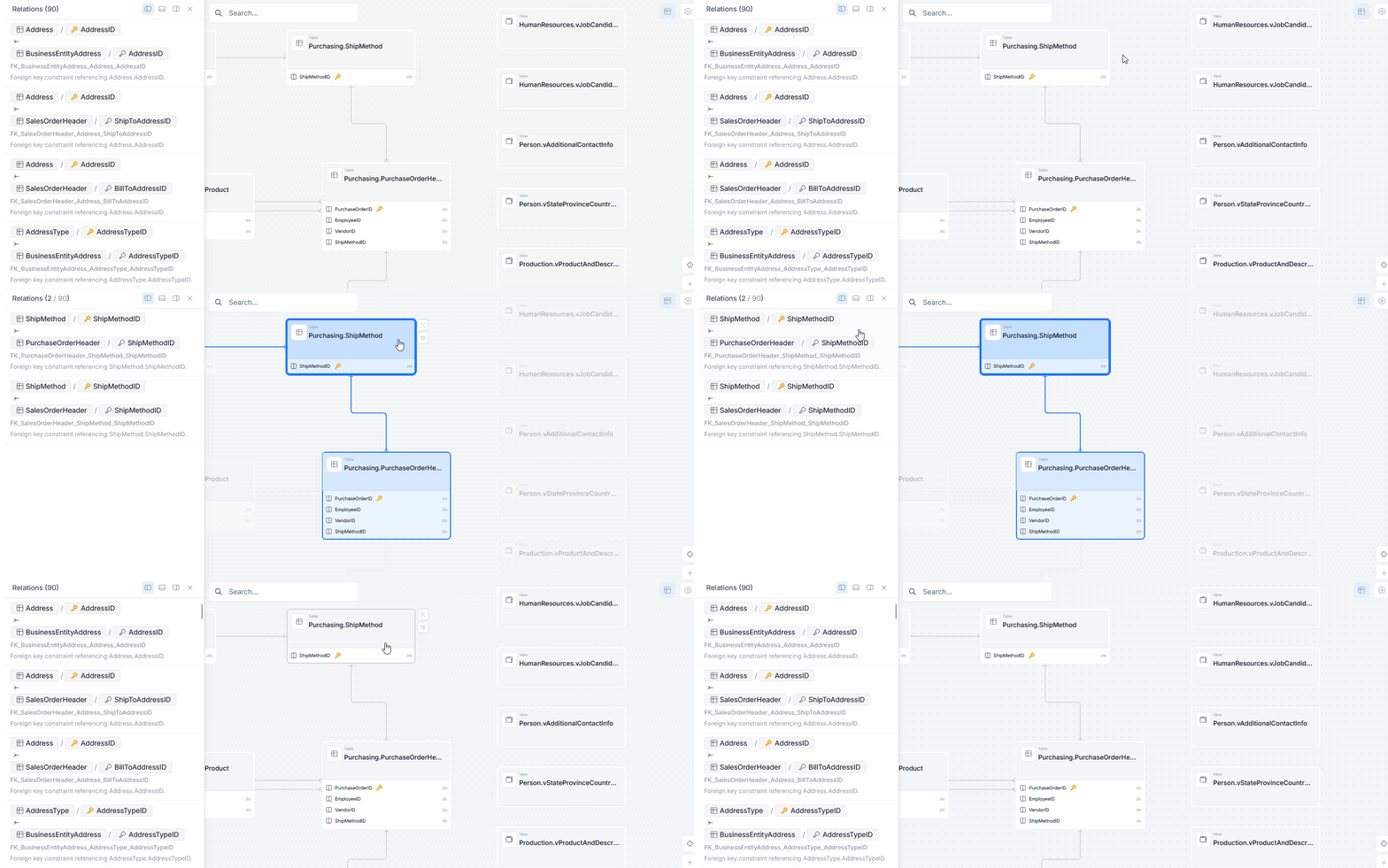
Diagram settings
You can also modify what information is displayed, and in what manner, using the options icon in the top right part of the Diagram view.
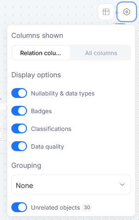
In the settings you can:
- decide whether all columns or only the columns relevant for the diagram are displayed for each object
- decide which (if any) of the object badges are shown
- group the objects of your diagram
- decide whether to show unrelated objects
Grouping
The Grouping section in settings allows you to visually cluster objects in the diagram based on:
- their shared database schema information
- their shared categorization (same Business Domain, Data Domain, Area or Data Product)
Different groupings are marked as different colored boxes, each containing their respective objects.
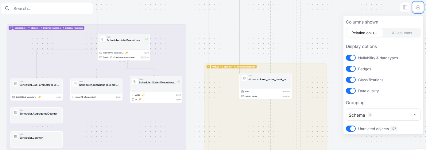
Only one grouping filter can be applied at a time — so you can group objects by either their database schema or the Data Products they are linked to, but not both at the same time.
Indicators on diagrams
Different nodes of an ERD diagram represent different objects. Those objects can have different significance in your organization — some might contain essential data, while others might require frequent checks to ensure that their data is correct. This information should be easily accessible, which is why object nodes in ERD diagrams can display it as badges.
Data Quality
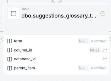
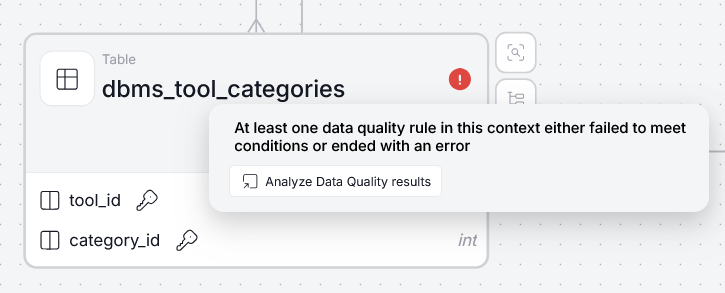
If your object has any Data Quality Rule Instances assigned, an indicator in the top right corner of its node lets you quickly preview the status of the Data Quality checks. A green indicator signals that all checks have passed, while a red one indicates that at least one has failed.
Data Quality Indicators
Hovering over an indicator triggers a tooltip that lets you navigate directly to the Data Quality tab to investigate the results.
Data Classification
Results of your Data Classification assignments are represented as pill-badges underneath an object's name. Each badge displays the name of an applied Data Classification Protocol.
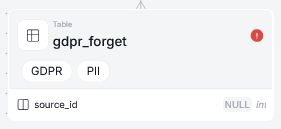
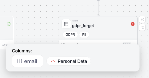
Hovering over an indicator shows the object's classified columns along with the category they received and its sensitivity level.
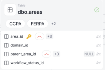
If more than two classification protocols apply to an object, some of them are hidden by default, under a + sign. Hovering over it reveals the rest of the classifications.
Badges
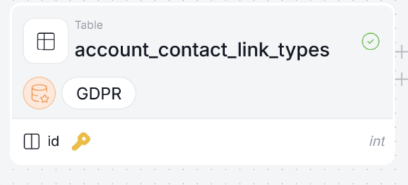
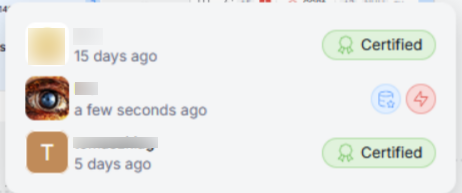
User-assigned badges are also displayed on diagram nodes.
Hovering over a badge shows the badge's name and the user who assigned it.
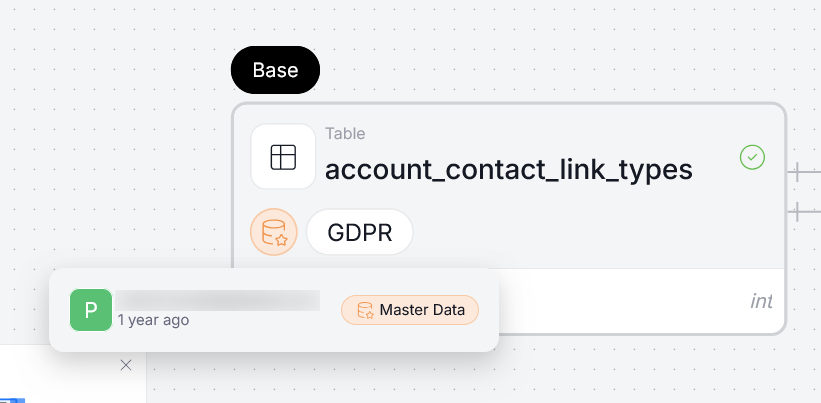
If one user added multiple badges, only their name is displayed and the badge names are omitted.
Asset diagrams
ERD diagrams are also available for single assets. In general, they follow the same conventions as database diagrams, with a few differences.
References
Asset diagrams mark referenced and referencing sources differently. A referenced source is one the current asset draws a column from, while a referencing source is one that draws from the current asset. Dataedo marks referenced sources in purple, and referencing sources in light blue.
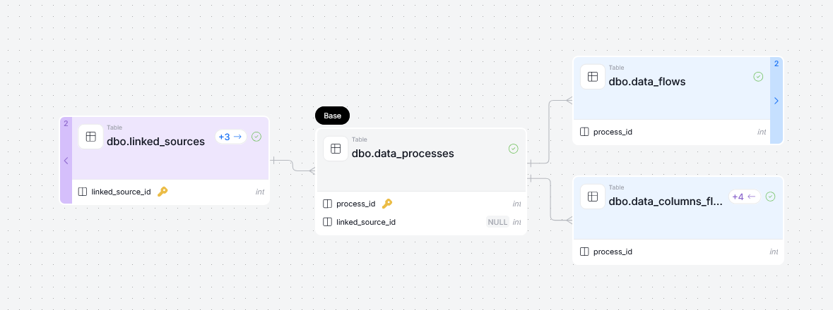
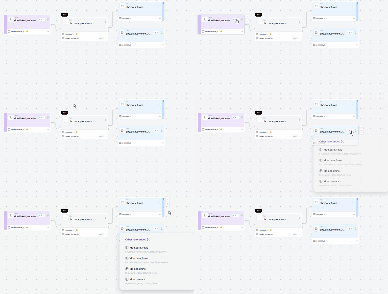
Some objects can serve as a referenced or referencing source for other assets too. These relations are marked by colored arrows. Hovering over them reveals the list of other related sources.
Extending asset diagrams
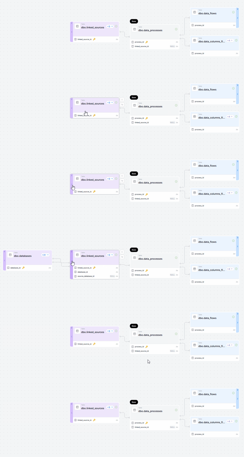
Just like Lineage Diagrams, ERD diagrams for assets also start out in the most local scope of an asset (its most immediate referenced and referencing sources). If you want to expand the ERD context, you can do so using the buttons at the edge of a diagram node.
Area diagram
Domains' areas also contain ERD diagrams that represent relationships between objects linked to your area, and other entities in the repository. You can view them by navigating to an area's Diagram tab.
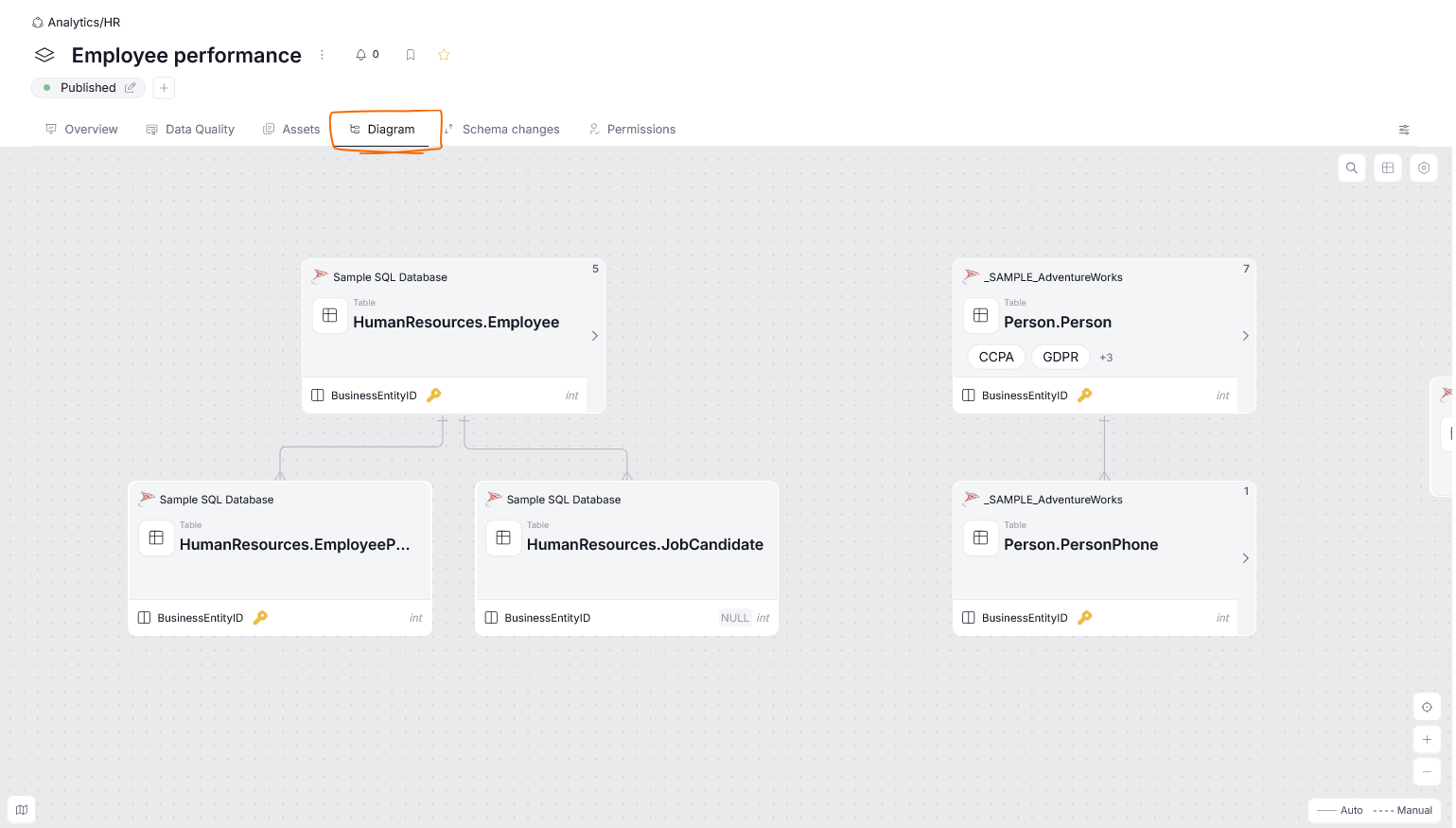
The default diagram is created automatically based on the existing links between your assets. The diagram initially displays only the assets that are linked to the currently viewed area. Navigating the diagram works the same way as with other ERD diagrams.
However, you might not always be happy with the diagram's default layout — you might not like how certain assets are ordered, or want some assets that are not linked to the domain to be shown nonetheless. You can make those changes using the diagram's Edit mode.
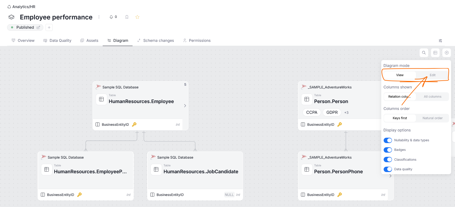
Editing area diagrams
The area diagram editor supports a wide range of changes and customizations you can use to make the diagram as detailed or informative as you would like.
Basic actions
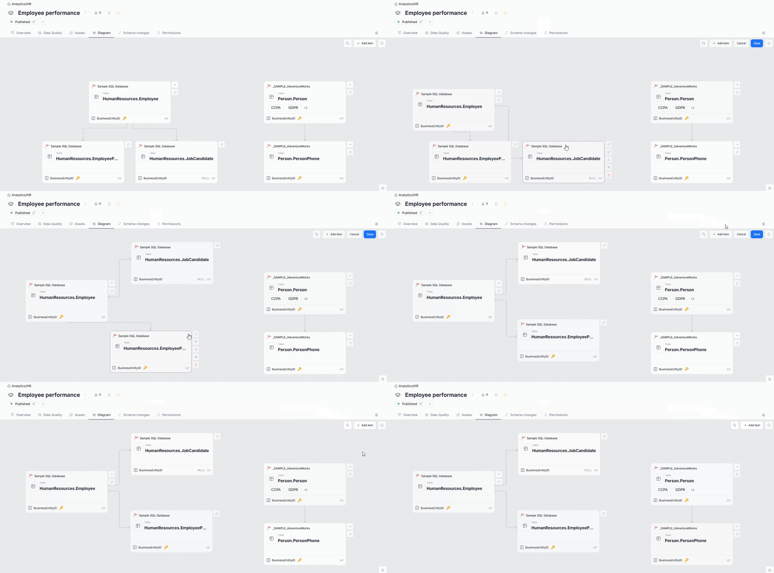
The first type of change you can make is rearranging the diagram's layout. When you move a diagram node to a new position, it stays in place after saving.
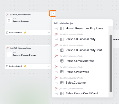
You can also enrich the diagram by adding links to existing nodes, using the add related objects button. This displays a list of objects related to that node via its own ERD diagram, letting you extend the current diagram with any of them.
Adding items
You can also add new items to the diagram. To do so, click add item and select what you want to add.
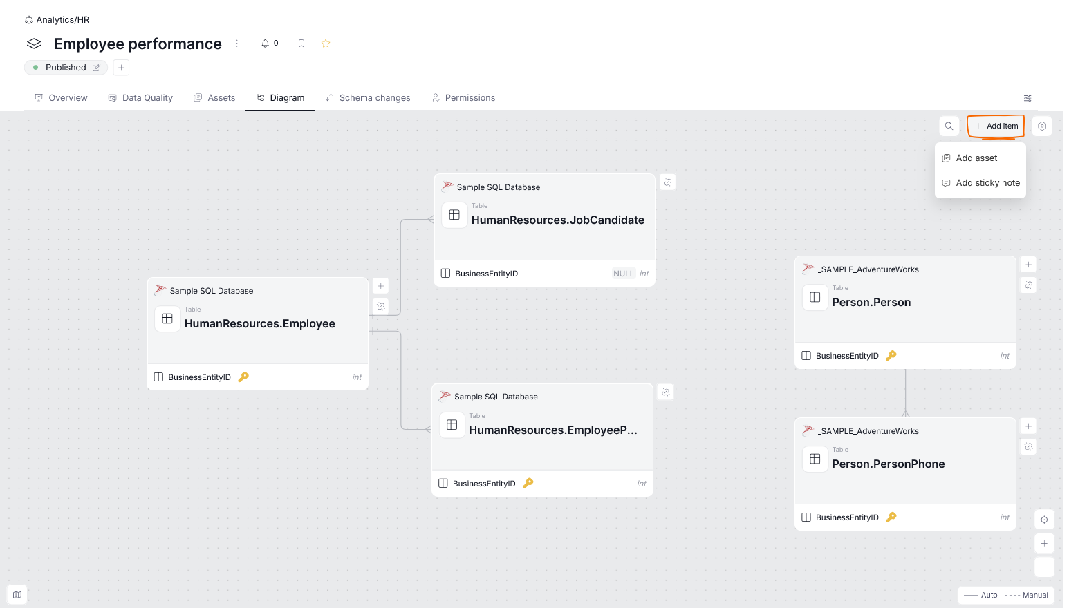
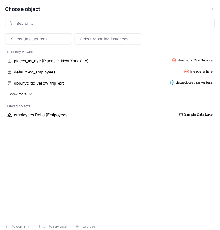
Selecting add assets opens a popup where you can select an asset to add to the diagram. Clicking an asset adds it to the diagram editor automatically.
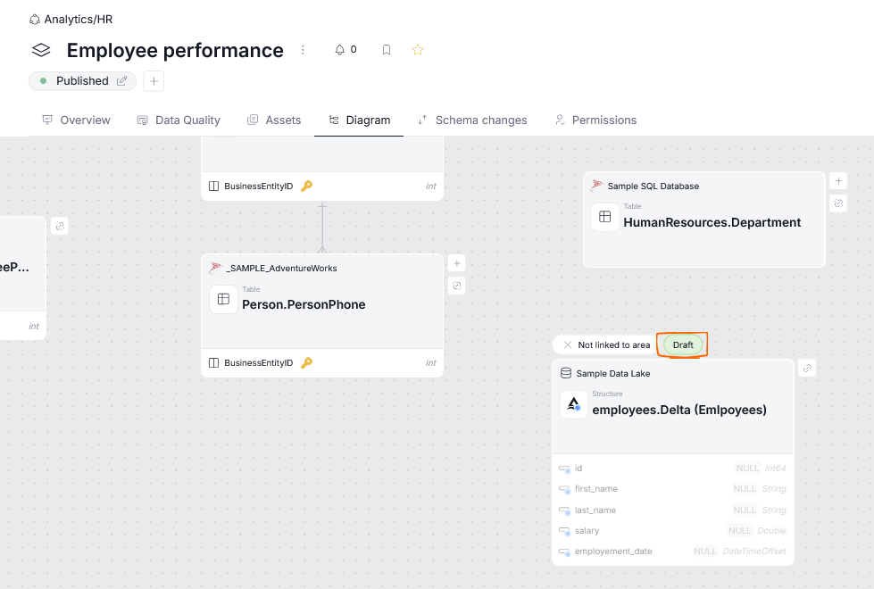
The added asset remains in a draft state until you save your changes.
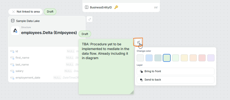
Another item you can add is a sticky note. A sticky note does not represent any asset — it is instead a memo or informative visual element that you can place anywhere on the diagram.
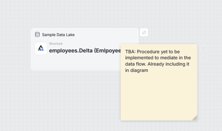
Clicking the edit button next to a sticky note gives you the option to change its color and the layer it is placed on, since a note can be positioned behind or in front of diagram nodes.
Node actions
Each node in an ERD diagram can be additionally customized.
Link/unlink from an area
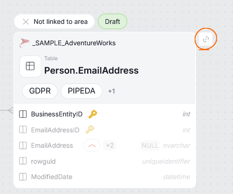
Assets in your area's ERD diagram do not necessarily have to be linked to that area. For example, you might want to include tables that provide data to a crucial view in your area on a diagram, without having those tables directly linked to the area. When editing a diagram, you can add or remove an asset from the area using the link/unlink buttons.
Link/unlink buttons
Edit node
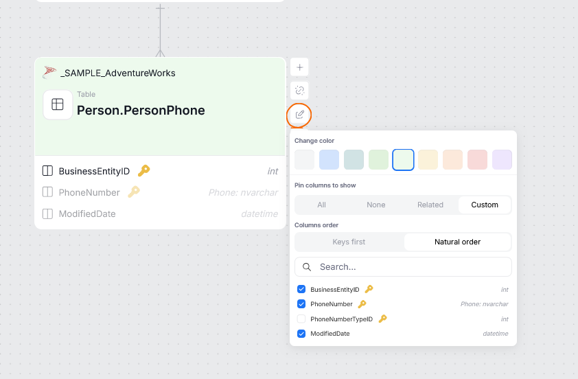
You can use the edit button next to a node to:
- change the node's color
- decide which columns should be shown on that node by default
- decide the column order
Delete node
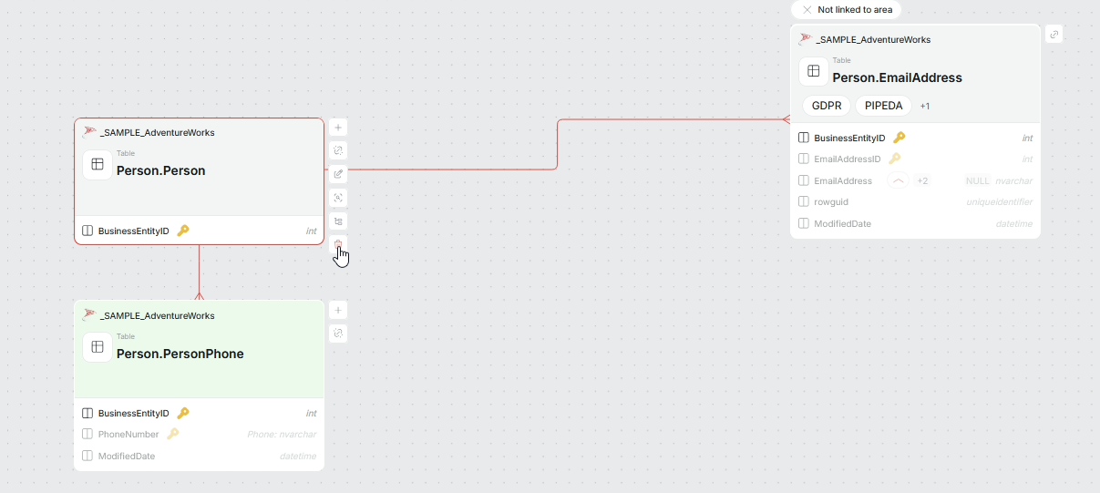
Deleting a node removes that node and every node reachable from it through outgoing links from the diagram. It does not remove the object from your repository
You can use the trash can icon to delete a node. Hovering over that icon highlights in red the nodes that will be removed.
Saving changes
All changes have to be saved using the save button.
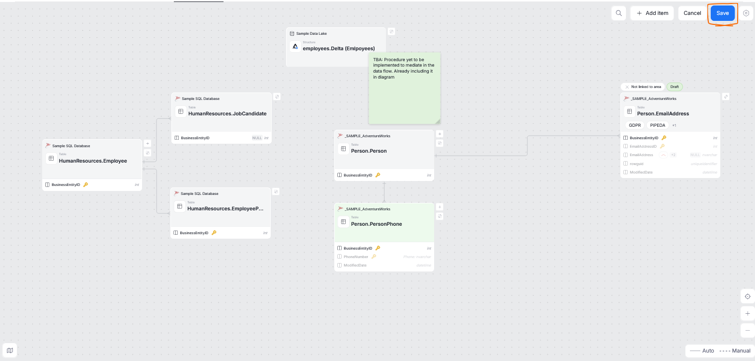
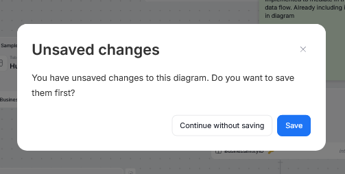
If you try to leave the diagram page without saving your changes, Dataedo warns you and gives you the option to save before leaving.
Two views
If you make any changes to an area's diagram, you can switch between the initial, auto-generated diagram and the one you tailored to your needs, while in view mode.